
How to measure axial straightness of bore, tube, and barrel IDs
Published on March 4, 2019
Axial (or axis) straightness is a tolerance that controls how much a part’s axis is allowed to curve.
Measuring axial straightness of bore, tube, and barrel IDs is often critical to ensuring proper component function. While measurements in such tight spaces can be challenging for many instruments, Novacam 3D metrology systems obtain these measurements rapidly, in a non-contact automated manner, and with micron (and often sub-micron) precision.
How is this done?
Small probes for narrow spaces
Novacam provides two 3D metrology systems for measuring inside diameters (IDs): the BoreInspect and TubeInspect. Both systems use small-diameter side-looking optical probes that come in a range of sizes and lengths. (As of today, the thinnest probe, with 0.5 mm diameter, measures IDs as small as 1 mm.)
To acquire surface measurements, the side-looking probe shines a beam of light at the ID surface and collects the signal reflected back from the surface. While the probe traces a predetermined path through the ID, measurements are done in a point-by-point manner at a rate of up to 100,000 3D points per second. The path may be linear, circular or spiral.
For the fastest axial straightness measurement, the operator would request 3 distinct circular profiles of the ID.
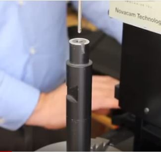
TubeInspect small-diameter probe about to enter a 5.6-mm diameter bore
Axial straightness calculation
Axial straightness is a 3D tolerance. The axis being controlled must lie within the volume of a cylinder defined by the tolerances.
From the 3D point cloud data generated by Novacam 3D metrology systems, the component axial straightness is calculated by geometrical dimensioning and tolerancing (GD&T) software (typically PolyWorks InspectorTMsoftware).
The two images below show axial straightness measurements calculated from 1) 3 circular profiles, which is the most time-efficient method, and 2) from a high-density spiral scan of the ID.
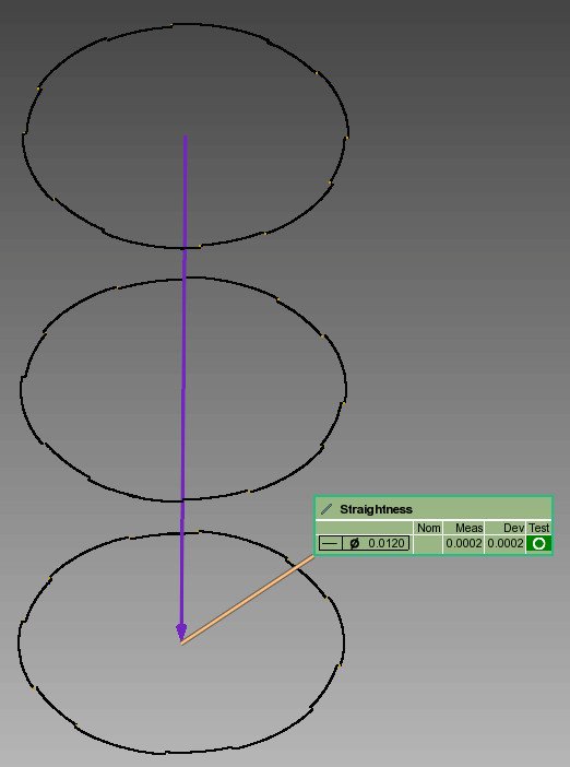
Bore ID straightness from 3 profiles
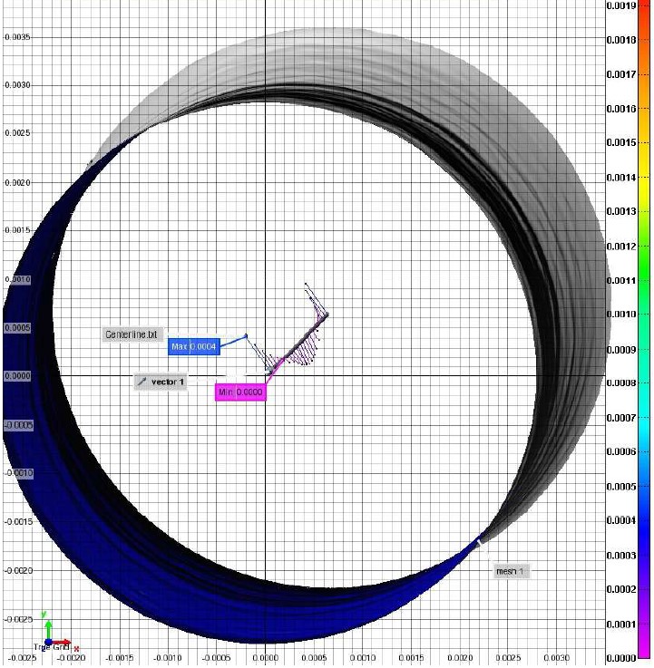
Straightness deviation map generated from a high density spiral scan.
Precision of measurement
With Novacam ID measurement systems, the repeatability (standard deviation of type1 Gauge R&R) of straightness measurements is typically better than 0.5 µm (0.00002”). Here is an example:
- The TubeInspect was used to measure GD&T straightness of two bores. The operator repeated the measurement 10 times for each bore and then used PolyWorks InspectorTM software for straightness calculation and reporting. Here are the results:
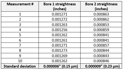
Repeatability (standard deviation of type1 Gauge R&R) of axial straightness measurement
All measurements can be automated
Parts with tight GD&T straightness tolerances include automotive or aerospace valves valves, shafts, hydraulic cylinders, medical tubes, zirconium tubes, safety valves, fuel rails, defense bores and barrels, and extruder dies.
With both BoreInspect and TubeInspect, users easily automate the entire process of ID scanning, straightness calculation, and the reporting, with go-no-go value assignment. The same goes for the measurement of other GD&T parameters such as ID or OD roundness, concentricity, cylindricity, etc. But we will leave discussions of those parameters for another day.
Do you need to measure GD&T axial straightness inside (or outside) your component?
See related product pages for: