Can I generate a CAD model from my 3D point cloud?
Published on December 16, 2019
This is a question we get asked occasionally, even though generating CAD models is not the principal function or focus of Novacam 3D metrology systems. Novacam systems provide automated non-contact high-precision measurements for industrial applications. To measure, you don’t need a CAD.
Still, some of our clients’ ultimate goal is reverse engineering of high-precision parts. They wonder if the 3D point cloud or the STL file (mesh) that Novacam systems generate can be used as a starting point for creating a CAD model.
Click on images for close-up view
The answer is yes… not directly, but we can get you started
You’ll need to follow a step or two beyond the software supplied with our systems.
First, some definitions of the types of data produced by Novacam systems (described in previous blog article):
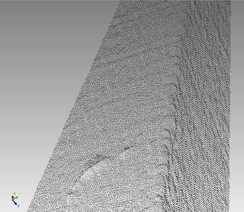
- A 3D point cloud is a set of data points associated with X,Y,Z coordinates. In the context of 3D scanning, the point cloud represents the set of points measured on the object surface and maps the surface in a 3D space.
- A mesh is a representation of the 3D object using a set of polygon surfaces. It offers a continuous view of 3D measurement data, much like stretching a skin over the measured 3D points. The mesh can be created from a 3D point cloud by, for example, connecting adjacent points with triangle surfaces. Novacam system software can also output the acquired 3D scan data directly in mesh (STL file) format.
What is a CAD model?
- A CAD model is commonly defined as a 2D or 3D representation of a mechanical design of an object drafted using vector-based graphics. It typically includes information such as dimensions and tolerances.
So, what’s involved in making a conversion to CAD?
Conversion of a 3D point cloud to a CAD model is basically a 2-step process.
Step 1) Extract geometric forms from the 3D point cloud
To convert a 3D point cloud to vector-based graphics, you must first start by segmenting the point cloud, i.e., identify groups of points as representing geometric forms such as cylinders and planes. Various software – both professional and free – exist to help in this step.
The PolyWorks InspectorTM GD&T software, which Novacam offers as an option with our systems, can be used at this stage. It provides tools for extracting geometric features such as cylinders, cones, planes and spheres from the 3D point cloud. You can also impose constraints on the extracted geometrical features – for example, some features can be made coaxial, parallel or perpendicular to each other – to bring their aspects closer to what an original (CAD) design would be. Here is PolyWorks Inspector tutorial video on this subject.
Step 2) Export the segmented 3D data in IGES format for use in CAD software of your choice
From the PolyWorks Inspector, you may export the extracted features into an IGES file, which can then be used for the creation of a CAD drawing using the software of your choice.
What else should I consider in this process?
First – whatever software you use, the above two-step process is not fully automated – human intelligence is still required to interpret the raw data correctly. Patience is required and, when needed, online tutorials and discussions specific to each software package are often a great source of know-how.
Second – when you need to produce high-precision 3D scans and CAD models of parts with hard-to-reach surfaces, keep in mind that Novacam’s BoreInspect and TubeInspect offer a unique avenue for measuring surfaces in tight spaces in a non-destructive manner and without the use of rubber replicas.


