Barrel metrology
Automated barrel inspection and 3D measurement

The inner surface quality of barrels highly contributes to firearm safety and accuracy. This is why barrel manufacture processes must be controlled through rigorous barrel ID inspection and 3D measurement. Until recently, gauging of barrels has been carried out with pin gauges, star gauges, and air gauges. Also, video borescopes have assisted in defect detection. However, data provided by these methods are minimal and not adequate for a thorough evaluation of ID parameters. To better control the barrel manufacture process, firearm manufacturers increasingly look for more precise, comprehensive, and automated barrel ID measurements. The reasons are:
- Growing need for 3D modeling and for quantitative evaluation of a wider range of ID parameters.
- The need to speed up and improve quality control of both intermediate and final product when the production chain is being automated.
In answer to these needs, NOVACAMTM non-contact 3D metrology systems increase the range and precision of barrel ID measurements and facilitate automation. As a result, manufacturers improve their process control and product quality, decrease scrap, and increase savings.
Download application note “Automated Barrel Inspection and 3D Measurement” [PDF, 19 pages, 2.5 MB]
System Parameters
for Non-contact Barrel ID Measurement
with NOVACAM 3D Metrology Systems
- Measured barrel ID from 4 mm to 155 mm
- Micron measurements precision
- Up to 100,000 measurements (3D points) per second
- Ability to measure:
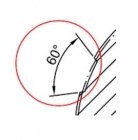
- Rifling parameters – widths and IDs of lands and grooves, twist rate, flank angles, polygonal rifling measurements, etc.
- Straightness, roundness, taper, runout, etc.
- Surface defects
- Roughness
- Chatter
- Cross-holes, grooves, steps, undercuts, and slots
- Chamber geometry – body, shoulder(s), neck, freebore, lead
- Preconfigured for automated barrel, rifling, and chamber inspection reports
- User-configurable automated inspection sequences along linear, circular, or spiral paths within the barrel ID
Two systems for barrel ID measurement: TUBEINSPECT and BOREINSPECT system
Novacam offers two non-contact 3D metrology systems for barrel inspection – the TUBEINSPECTTM system and the BOREINSPECTTMsystem.
Both systems:
- Measure IDs of rifles, shotguns, handguns as well as large caliber barrels
- Measure GD&T parameters (e.g., straightness, roundness, concentricity, and rifling dimensions) and roughness with a single probe
- Are easily integrated in firearm manufacturer’s lab or in automated industrial inspection setups
- Produce 3D data used for automated user-configurable reports, for SPC (statistical process control) monitoring of production, and for gaining manufacture process insight that leads to process improvement.
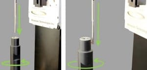
While the measurements are the same, the mechanics of the measurement process differ.
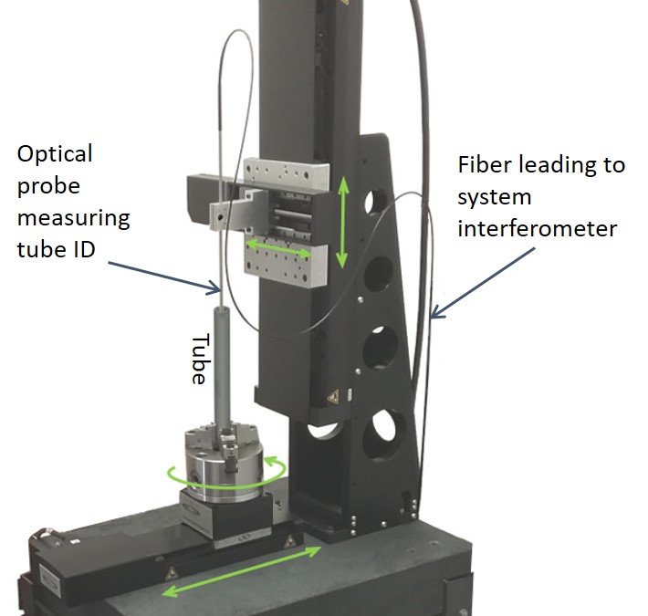
- With the TUBEINSPECT system, the part is rotated.
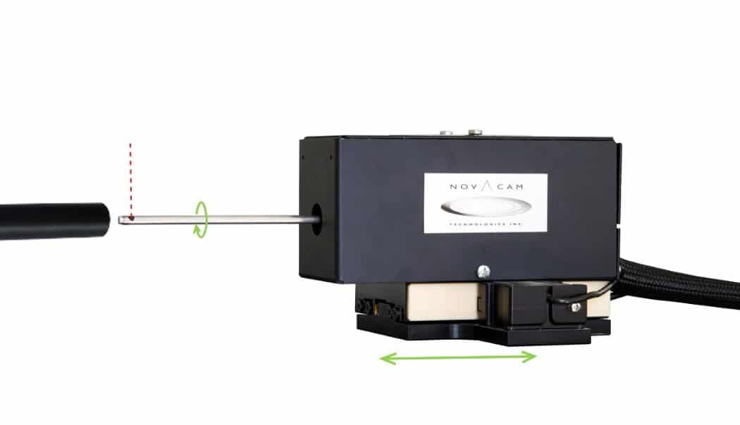
- With the BOREINSPECT system, the probe rotates inside a stationary bore.
TUBEINSPECT system
BOREINSPECT system
The TUBEINSPECT system can also measure outside diameters
(of barrels, reamers, mandrels, etc.)
Many manufacturers appreciate the capability of the TUBEINSPECT system to measure not just the barrel ID but also:
- The outside diameter (OD) of barrels. In most cases, there is no need to change probes.
- The OD of reamers, mandrels and other machining tools. Periodic high-precision inspection of barrel machining tools helps avoid scrap that occurs when tools are out of spec. For mandrels for example, the TUBEINSPECT system is able to measure lands and grooves, pitch (twist rate), straightness, etc. Regardless of the rifling process – whether cut rifling, broach rifling, button rifling or hammer forging – manufacturers gain superior control on the machining & finishing processes.
More on the selection of the system for your barrel inspection application is available further below.
First though, let’s look at the barrel ID data obtained by both the TUBEINSPECT and the BOREINSPECT system.
Format of raw measurement data
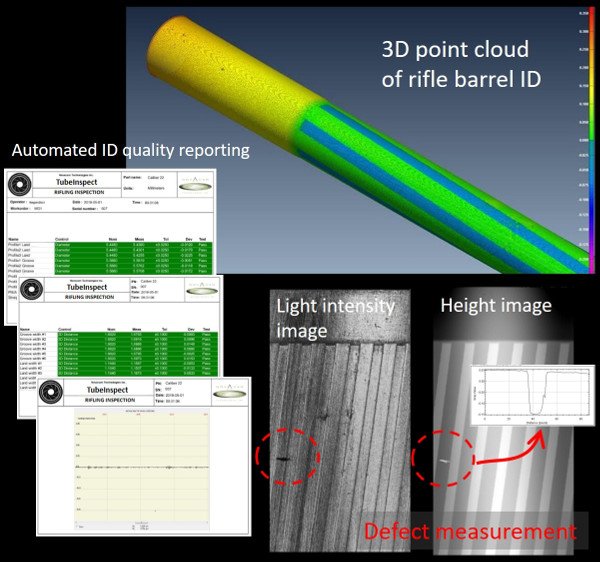
The TUBEINSPECT and the BOREINSPECT system each generate 3 sets of raw data simultaneously: 3D point cloud, light intensity map, and height map. For example, here below is ID data acquired by the TUBEINSPECT system from a scan of an 18”, .22 caliber rifle barrel (46 cm long, 5.6 mm diameter).
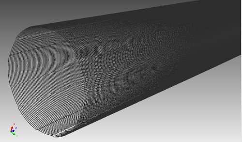
The 3D point cloud data is used for both interactive and automated analysis of a 3D model of the bore and for calculating 3D parameters.
This particular high-resolution scan comprises ~4.7 million 3D points. The user selected:
- Sampling step in axial direction: 0.1 mm
- Sampling step along rotational path: ~ 0.017 mm (1,050 points/ rotation)
Options for barrel data analysis
- The TUBEINSPECT and BOREINSPECT systems come preconfigured to produce automated barrel (and rifling) inspection reports. These reports are described in more detail further below.

- The generated 3D point cloud data may also be viewed and analyzed with third party CAD/GD&T software in conjunction with NOVACAM barrel measurement analysis tools. These tools are geared towards speeding up and fully automating the repetitive tasks of bore data processing and go-no-go reporting. The majority of these tools are available as an extension to InnovMetric PolyWorks InspectorTM GD&T software, although support is also available for other packages such as Geomagic.
- The generated height and light intensity maps may be viewed from within NOVACAM data acquisition software for analysis of defects such as burrs, erosion, pitting, corrosion, or wear. More on this below.
- For clients who prefer to process the raw barrel ID data themselves using their own display and analysis software, a range of raw data options are available: 3D point cloud, height image, intensity image, roughness, diameter, STL file, and more.
Interactive data visualization
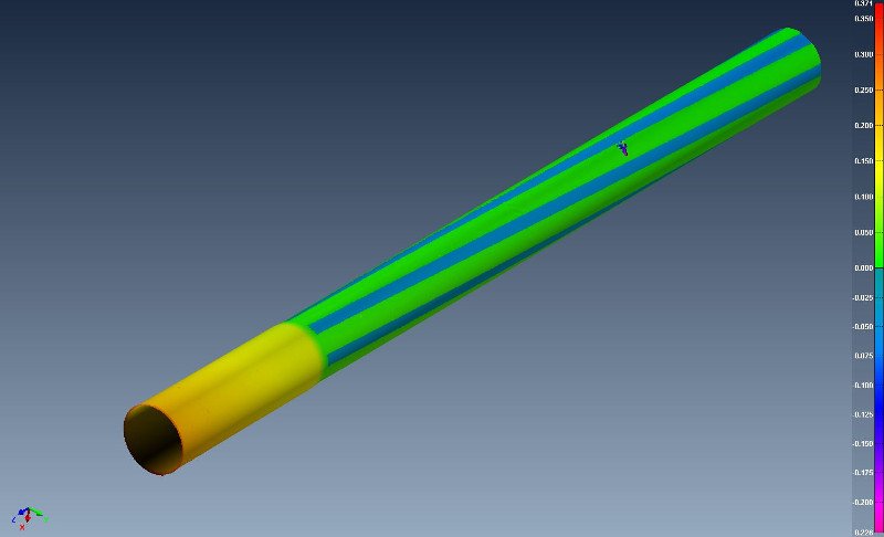
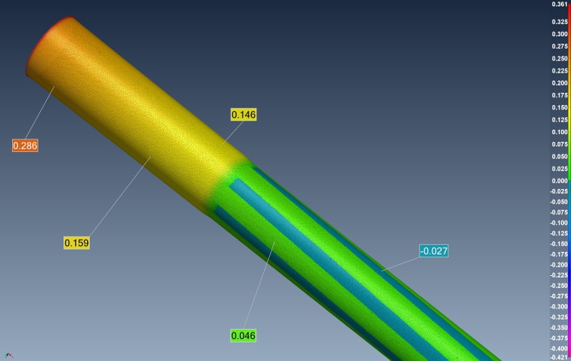
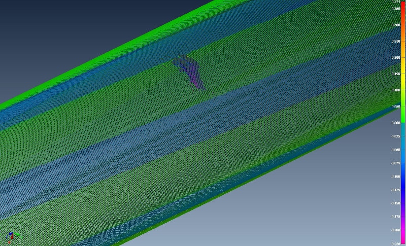
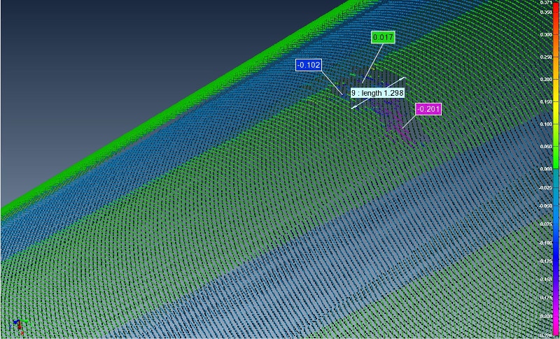
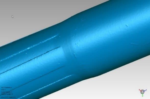
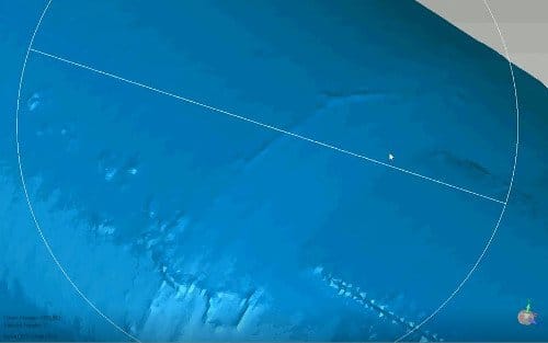
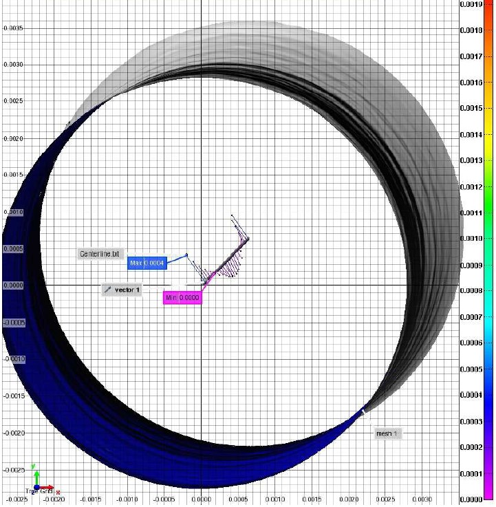
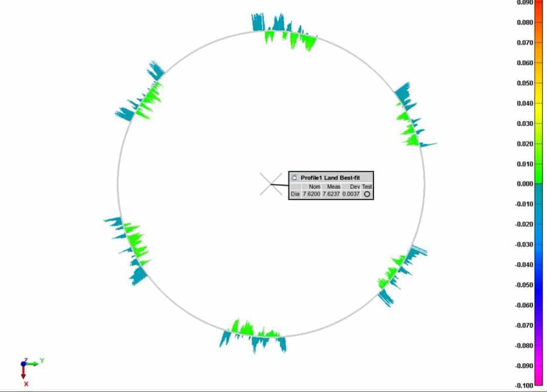
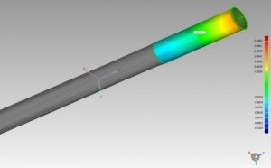
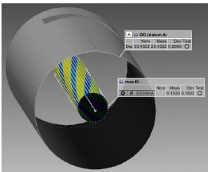
Novacam offers third party CAD/GD&T software PolyWorks InspectorTM as an option with its TUBEINSPECT and BOREINSPECT systems. This software enables full viewing and analysis of the acquired point cloud as a 3D interactive map. As shown in the images below, views such as deviation maps (deviation from perfect cylinder or from a CAD) help provide key insight into bore machining processes – including gun drilling, reaming, rifling, stress relieving, contouring, chambering, or finishing – as well as into the effect of wear.
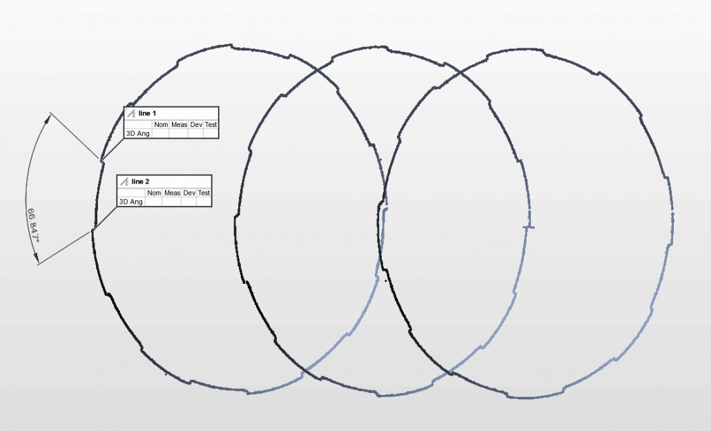
The images above show high-density point cloud data. Such high level of detail is not always necessary; when inspection time is of the essence, several profiles inside a barrel provide an excellent basis for fast quality control assessment. As shown below, users can run an inspection sequence consisting of several barrel profiles, and use NOVACAM barrel measurement analysis tools to measure key barrel measurement parameters.
Barrel analysis tools
With NOVACAM 3D metrology systems, users may choose to:
- Evaluate the barrel ID data with respect to user-defined criteria (GD&T, inner feature specifications, roughness, and defect inspection) or with respect to a reference CAD model.
- Carry out the inspection, analysis, and reporting interactively or in a fully automated mode. To automate repetitive tasks, users configure Scan Definitions, which comprise measurement sequences and subsequent reporting. Once a Scan Definition is built, it can be named and saved for later reuse.
Automated rifling analysis – lands, grooves, twist rate, straightness
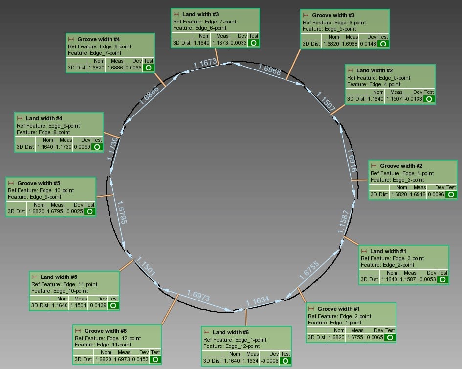
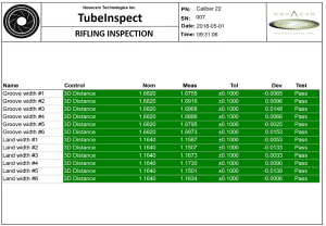
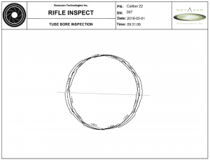
As an example of a user-configured inspection sequence, a Scan Definition called CAL22 was configured to measure, analyze, and report on three circular profiles at specified depths within a 22-caliber barrel. Nominal and tolerance values for each parameter were included in the definition.
This particular Scan Definition generates a multi-page report. Click sample pages from the report for close-up view.
With barrel inspection reports such as these, the operator is quickly informed of the barrel’s conformity to specified tolerances.
Below are more details on these and other measurements that can be obtained with NOVACAM 3D metrology systems and included in barrel inspection reports.
Straightness measurement
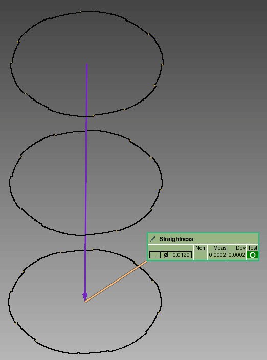
Barrel straightness may be calculated from 3 or more circular profiles (see below left) or from a high-density scan of the bore ID (see below right).
Notably, the repeatability of straightness measurements acquired with NOVACAM systems is better than 0.5 µm (0.00002”).
- Example: GD&T straightness was measured for 2 bores. For each bore, the measurements were repeated 10 times. PolyWorks InspectorTM software was used for straightness calculation and reporting to obtain the following results:
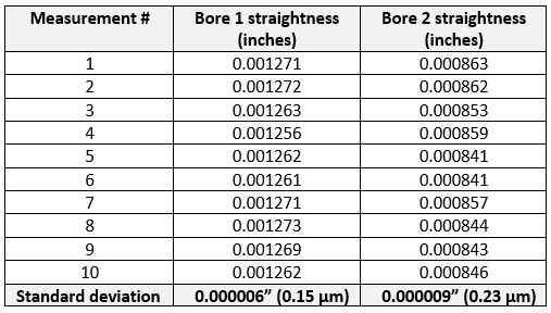
Repeatability of straightness measurements
Pitch (twist rate) measurement
Rifling twist rate may be calculated whether the twist is uniform or variable.
Variable twist (also known as “progressive twist ” or “gain twist”) is automatically calculated from a series of circumferential ID profiles of the barrel. The number and density of the profiles is set by the user.
Roundness (circularity) measurement
Roundness may be measured for both smoothbores and rifled bores.
Surface profile measurement – cylindricity, conicity, taper, etc.
Cylinder, cone, and taper tolerancing, as well as any other profile tolerancing, is supported by Novacam through powerful GD&T software like PolyWorks InspectorTM.
Runout measurement
All runouts may be measured, including:
- Runout between the chamber and the bore
- Runout between grooves and lands
- Runout between barrel OD and ID .
Roughness measurement and analysis
A roughness profile of a selected section of the barrel is available directly from NOVACAM acquisition software and may also be included as part of an automatically generated barrel inspection report. Read more on roughness measurement with NOVACAM 3D metrology systems.
Cross-hole measurement
Gas-port holes drilled in automated rifles can be measured and visualized.
Chatter measurement and analysis
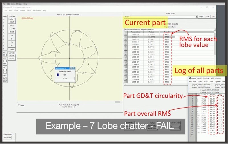
NOVACAM 3D metrology systems provide fast and reliable non-contact chatter measurements on IDs of barrels. The TUBEINSPECT system will also measure chatter on barrel ODs or on the ODs of barrel machining tools.
NOVACAM Chatter Analysis Software mathematically analyzes the pattern of chatter, and characterizes it by parameters such as the amplitude or RMS (root mean square) value for each lobe value. Parts may be categorized as PASS or FAIL as per user criteria.
Read more on bore ID chatter measurement with NOVACAM systems.
Defect inspection
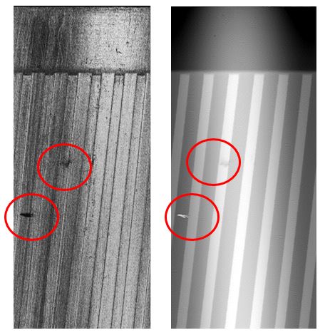
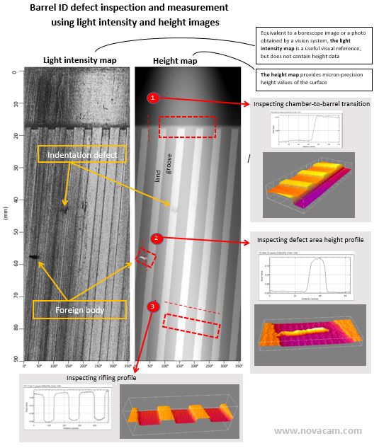
With NOVACAM 3D metrology systems, defect detection and reporting may be completely automated. Nevertheless, for clients who want to also look for defects interactively, the height and light intensity maps generated in addition to 3D point clouds are excellent tools for fast bore ID defect detection and analysis. The following maps represent the ID of the first 9 cm of a .22 caliber (5.6 mm diameter) rifle barrel.
Which system is more suitable for my application – TUBEINSPECT or BOREINSPECT?
Both the TUBEINSPECT system and BOREINSPECT system include the following components:
- MICROCAMTM-3D/4D interferometer (19” rack-mountable component) that provides light source to the optical probe and carries out optical and electronic processing of the measurements
- Fiber-based side-looking optical probe whose length, diameter, and optical properties (spot size, standoff distance) are selected according to client needs. Several probes may be multiplexed to one interferometer for additional return on investment (ROI).
- Motion controller (19” rack-mountable component)
- PC workstation (mini desktop size PC or laptop) that hosts NOVACAM data acquisition software and, typically, data analysis software
- Inspection station with motion components (linear and rotation) that are standard for standard supported barrel calibers or customized to client requirements
- Calibration rings.
The main difference between the two systems is the manner in which they scan the barrel ID:
The TUBEINSPECT system rotates the measured barrel around the optical probe.
The BOREINSPECT system rotates the optical probe within the fixed barrel.
Videos showing BOREINSPECT system functionality:
The following chart outlines the common points and the differences between the two systems.
| TubeInspect | BoreInspect | |
|---|---|---|
| Common characteristics | ||
| Technology | low-coherence interferometry | |
| Type of scanning | Non-contact, optical, collinear scanning (enabling even the measurement of high-aspect-ratio features such as cross-holes, undercuts, etc.) | |
| Light wavelength | 1,310 nm, infrared | |
| Light bandwidth | Broadband light | |
| Pointer for alignment purposes | In-probe laser @ 650 nm | |
| Instrument safety | Class 1M laser product*: < 20 mW of infrared, < 5 mW of in-probe laser |
|
| Acquisition speed | 2,100 or 100,000 3D point measurements per second, depending on interferometer model selected (Microcam-3D or Microcam-4D) | |
| Sampling step along rotational path | user-configurable | |
| Sampling step in axial direction | user-configurable | |
| Light spot size (Lateral [XY-axis] resolution) | Variable, typically 13 to 22 µm (512 to 870 µin.) | |
| Key differences | ||
| Key differentiator | Rotates the measured barrel. The side-looking probe advances along the inside (or outside) wall of the rotating barrel to acquire the ID (or OD). | Rotates and advances the side-looking probe into the measured barrel, which remains fixed. |
| Rotational speed for spiral acquisition | Up to 2 rotations (circular profiles) per second with an upgrade to 6 rotations per second | Up to 30 rotations (circular profiles) per second |
| Probe positioning | Probe does not need to be positioned at the center of the bore; it only needs to remain at a fixed distance from the side wall. | Probe should be positioned close to the bore centerline (+/- 0.25 mm) to capture the entirety of ID features. For irregularly-shaped objects or slots or crevices, the probe can acquire the entire surface by scanning from several positions. |
| Benefits | ||
| Standard barrel diameter sizes** | Small caliber: .172 caliber (4 mm) .20 caliber (5 mm) .22 caliber (5.6 mm) .243 caliber (6mm) .26 caliber (6.5 mm) .284 caliber (7 mm) .308 caliber (7.62 mm) .323 caliber (8 mm) .357 caliber (9 mm) .40 caliber (10mm) .44 caliber (10.9 mm) .45 caliber (11.43 mm) .50 caliber (12.7 mm) Medium and large caliber: 20 mm - 90 mm | The same system standard barrel IDs are supported for BoreInspect as for TubeInspect, but depending on the application, different caliber ranges may require a change of probe. Note: Novacam’s extended range rotational probes (4.6-mm diameter) are capable of scanning barrel IDs from 6 mm to 30 mm – wider range than any other rotational probe currently on the market. |
| Barrel lengths** | Standard up to 40" (1000 mm) | Standard up to 12" (300 mm) |
| Barrel weight | Up to 250 kg is standard. Heavier barrels may require custom rotational stages. | Not applicable since barrel remains stationary |
| Unique advantages | Ability to scan:
|
|
| Extra bonus measurements | Ability to scan:
| Ability to scan:
|
| * Class 1M laser product: Visible and invisible laser radiation. Do not stare into beam or view directly with optical instruments. ** Non-standard barrel IDs and lengths can be accommodated with custom setups. With custom longer probes, bores as long as 6’ (1.8 m) have been scanned. A trade-off exists between probe diameter (which affects rigidity) and probe length. For longer probes, centralizers may be required. |
||
Conclusion
When it comes to firearm accuracy and safety, barrel ID quality is key. NOVACAM TUBEINSPECT and BOREINSPECT systems bring significant inspection capabilities to barrel manufacturers. These capabilities include high-precision barrel ID measurements, option for complete automation of the inspection process, and high level of versatility for inspection station setup. For manufacturers, the wide variety of measurements obtainable automatically with either TUBEINSPECT or BOREINSPECT system expands the range of quantifiable parameters while decreasing the inspection effort. More data and more efficient inspection means better process control. And cost savings.
Outside diameter (OD) measurements, which are additionally available with the TUBEINSPECT system, increase the return on investment (ROI) for barrel manufacturers on two fronts. First, barrel OD surface parameters may be measured to the same level of detail and precision as the barrel ID, ensuring better control on the final product. Second, using the TUBEINSPECT system to measure the OD of machining tools (mandrels, reamers, etc.) ensures that only to-spec tools are used. With such tool verification capability, product quality improves, scrap decreases, and savings increase.
Novacam encourages technicians and engineers in charge of barrel inspection to contact us to discuss your applications and particular challenges.
Related links
Download application notes:
- Automated Barrel Inspection and 3D Measurement” [PDF, 19 pages, 2.5 MB] – a printable version of this page
- Measuring Barrel Straightness [PDF, 2 pages, 0.2 MB]
Download info sheet on NOVACAM Barrel Analysis PolyWorks Package:
- NOVACAM Barrel Analysis PolyWorks Package [PDF, 0.3 MB]
Read about TUBEINSPECT system in research on barrel straightness
- “Analysis of the effect of bore centerline on projectile exit conditions in small arms,” KeAi Magazine [PDF, 0.9 MB]. Direct link to article.
Want to learn more?
