3D Geometry (GD&T)
High-precision non-contact 3D geometry measurements
Geometric dimensioning & tolerancing (GD&T) is a system used to define and communicate dimensional requirements on manufactured parts.
NOVACAMTM 3D metrology systems scan parts to generate 3D point clouds from which dimensions and GD&T parameters are rapidly calculated. The systems offer:
- Measurement precision better than 1 µm
- High-speed scanning: point-by-point acquisition at 2,100 to 100,000 3D point measurements per second
- Turnkey GD&T measurement, analysis, and reporting solution with optional purchase of PolyWorks InspectorTM, which Novacam offers as standard option. Alternately, clients have the option to process the data themselves with their own software.
- Ability to use the same system to for overall 3D surface metrology – measure roughness, chatter, or and/or defects – depending on system configuration
- Real-time feedback on manufacturing processes: application data is typically forwarded to process control software.
List of 3D measurements and GD&T parameters
The tables below list the types and examples of dimensional measurements and GD&T parameters that may be obtained from 3D point clouds generated with NOVACAM systems.
- Distance between valve-body bore axes (video)
- Depth of blind EDM slot (application page)
- ID of fuel injector nozzle (image on this page)
- IDs of automotive valve body bores (video)
- IDs of rivet holes (application page)
- IDs of barrel bores (application page)
- O-ring groove corner radius (blog article)
- Minor and major thread diameters (blog article)
- ID & OD of optical fibers and semi-transparent tubing (thickness application page)
- OD of fuel injector nozzle needle (image on this page)
- Cutting tool edge radius (application page)
- OD of rifle barrels (application page)
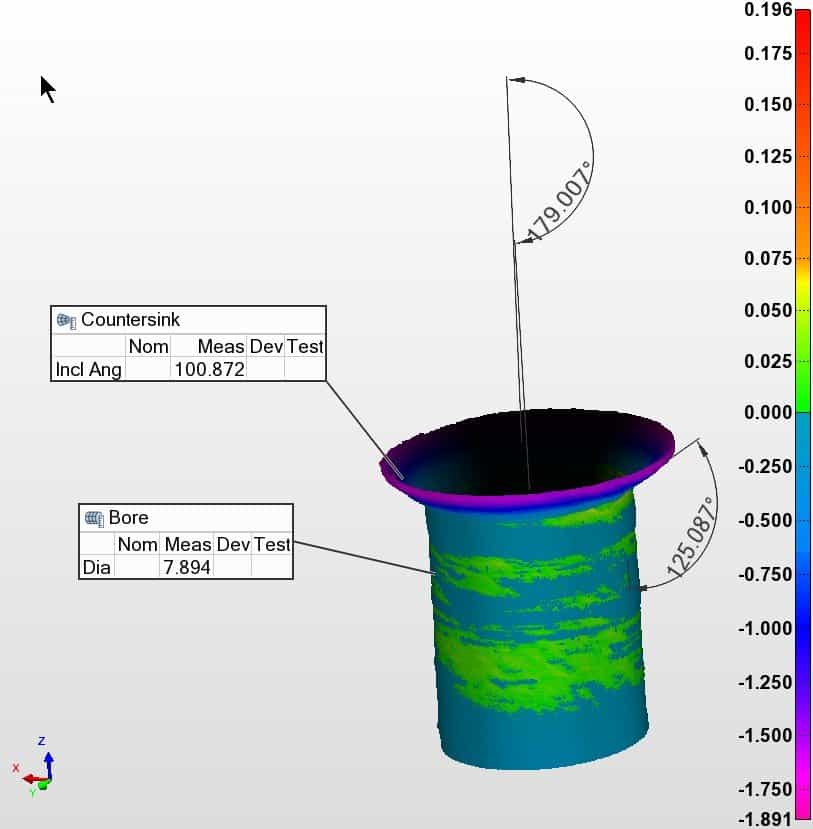
- Angles of chamfers and rivet countersinks, flank angles of barrel ID rifling, included angle of injector nozzle ID conical bottom (blog article)
- Slope angle on hypodermic needle lancet (featured in blog article)
| 3D geometric measurements | Examples | ||
| Measurements on INTERNAL surfaces (inside bores, slots, etc.) | Measurements on EXTERNAL surfaces | ||
| Distance (length, height, width) |  | ||
| Diameter* | 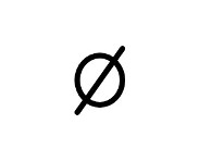 | ||
| Angle | 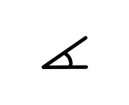 | ||
| *Repeatability of diameter measurements is in the 0.5 to 1.5 µm range (1σ) , depending on system configuration. |
|||
- Axial straightness of bore, tube or barrel IDs (blog article, application note)
- Axial straightness of cylinder, tube, or barrel ODs (application note)
- Area in between NGV blades (video)
- Heat exchanger slot surfaces
- Flatness of valve body mating surface (video)
- Rivet head flushness (application page)
- Bore holes (application page)
- Tube ID&OD (application page)
- Rivet hole & countersink Inspection (application page)
- Valve body bores(video)
- Barrels (application page)
- Cylinders (video)
- Tube OD (application page)
- Barrel OD (application page)
- Edge profile measurement (video)
- Incidence angle of cooling holes with respect to datum of turbine blade surface (application note)
- Angularity of bearing ID surfaces
- Angularity of bearing OD surfaces
- O-ring groove: perpendicularity of side wall to back wall
- O-ring groove walls(blog article)
- Heat exchanger slot surfaces
- Heat exchanger slot surfaces
- Valve body bores (video)
- Valve body bores (video)
- Inside-outside, inside-inside, outside-outside
- Rivet hole & rivet countersink (blog article)
- Barrel ID (application page)
- Cylinder ID
- Bearing ID
- Rivet hole & rivet countersink (blog article)
- Barrel OD (application page)
- Bearing OD
| GD&T parameter measurements | Examples | |||
| GD&T characteristic | Symbol | Type of tolerance | Measurements on INTERNAL surfaces (inside bores, slots, etc..) | Measurements on EXTERNAL surfaces |
| Straightness | 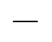 | Form | ||
| Flatness | 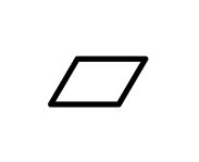 | |||
| Circularity (roundness) | 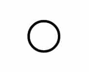 | |||
| Cylindricity |  |
|||
| Profile of a line | 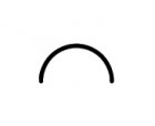 | Profile | ||
| Profile of a surface | 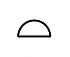 |
|||
| Angularity | 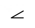 | Orientation | ||
| Perpendicularity | 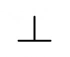 | |||
| Parallelism |  | |||
| Position | 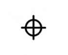 | Location | ||
| Concentricity |  | |||
| Symmetry | 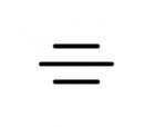 | |||
| Circular runout | 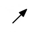 | Runout | ||
| Total runout | 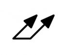 |
|||
Capabilities for 3D geometry measurement
NOVACAM 3D metrology systems offer:
- Non-contact, collinear scanning: the emitted and received light signals travel along an identical path. This means that high-aspect-ratio features such as slots, cross-holes or undercuts are easy to measure
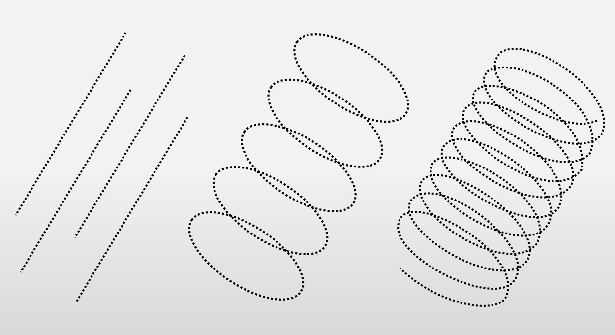
- User-configurable scanning protocol (point density, spiral pitch, scanning path). Users adjust scanning paths and scan point densities to satisfy their metrology requirements while minimizing their inspection cycle time.
- Customizable scan definitions (comprising scanning and reporting) that may be saved for later reuse.
- Option to provide measurement data to data loggers and SPC (statistical process control) software.
Advantages of system design that is modular & fiber-based
NOVACAM systems are modular and fiber based, meaning that the scanning optical probes are connected to the system interferometer with an optical fiber that can be several meters long. Thanks to the unique combination of Low-coherence Interferometry technology and fiber-based design, the systems offer significant advantages to our clients. These advantages include:
- Configuration versatility for both in-process and benchtop inspection
- Support for automation
- Ability to acquire long profiles
- Ability to measure inside small-diameter tubes, bores, etc. See inspection in hard-to-reach spaces
- Ability to measure surfaces with steps, grooves, channels, holes, and other high-aspect-ratio features
- Ability to scan surfaces that are reflective or nonreflective, smooth or rough, stationary or moving
- Ability to measure GD&T even in extreme temperatures or in radiation. See inspection in hostile environments.
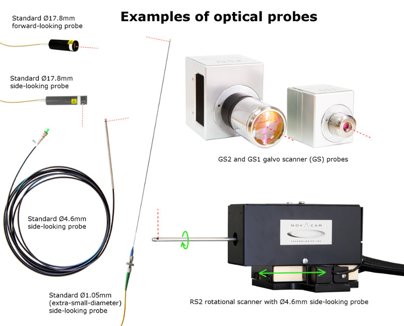
NOVACAM probes come in many designs and models, which include standard or small-diameter probes, as well as rotational scanners and galvo scanners – to satisfy the majority of high-precision inspection applications.
Cost-effective in-line inspection
NOVACAM fiber-based probes and scanners enable the integration of inspection directly into production process. They can be mounted:
- Above a continuously moving web
- Adjacent to a rotating part (cylinder, shaft, etc.)
- Inside a machining center
- On robot arms.
With continuous monitoring and real-time feedback on a manufacturing processes, dimensional variations and out-of-spec characteristics are identified promptly, helping avoid or minimize losses, while preserving quality and yields.
Probe multiplexing for additional return on investment (ROI)
Multiple probes may be multiplexed to a single NOVACAM MICROCAM interferometer with the addition of an optical switch. With this setup, probes take turns acquiring measurements on several aspects of a production line.
Do you need to measure your dimensional geometry precisely and efficiently?
Related links
Contact us or request free sample analysis to see if NOVACAM 3D metrology systems are suitable for your 3D geometry or GD&T measurements
