
Non-contact 3D measurement of CMP pads
Measuring System: NOVACAMTM OPTICAL 3D PROFILOMETERTM or SURFACEINSPECTTM system
Keywords: chemical mechanical polishing, high-precision, inspection of high-aspect-ratio grooves, channels, lands, profile, surface topography
Quality control of CMP pad surfaces
CMP (chemical mechanical planarization/polishing) pads are disk-shaped polyurethane foam pads used in semiconductor manufacture of advanced integrated circuit devices. In particular, the pads are used in the CMP process to flatten and polish silicon wafers to mirror-like finish.
The efficiency and efficacy of the CMP process depends in large part on the pad surface geometry. This is why quality control (QC) measurement of CMP pad surfaces takes place on two levels:
- During CMP pad manufacture, QC inspection includes measurements of the entire pad surface, including geometry measurements of the grooves and the lands (surface between the grooves). Manufacturers who obtain and track measurements on each pad are able to provide clients with QC reports.
- During the CMP process, QC inspection serves to determine the degree of surface wear of the pads caused by the the harsh CMP process. The depth of grooves, for example may be measured intermittently to ascertain that groove depth is adequate to keep using the same pad.
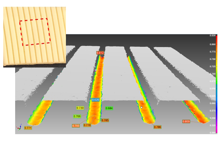
Micron-precision CMP pad inspection with NOVACAM non-contact 3D metrology systems fully supports strict surface quality control for CMP manufacturers. (Measurements shown are in mm, analysis done with PolyWorks Inspector industry-standard GD&T software).
CMP pad measurements: 3D, high precision, non-contact, automated
NOVACAMTM 3D metrology systems bring CMP pad manufacturers unprecedented capabilities for fast and comprehensive measurements. These capabilities include:
- Non-contact 3D surface measurements with 1 μm (40 μin.) axial resolution
- Ability to scan high-aspect-ratio features such as the narrow CMP pad grooves
- High-speed surface acquisition – up to 100,000 3D measurements/sec
- Dimensional and roughness measurements with the same probe
- Ability to obtain long profiles
- Facility for automated measurement both in lab and in high-volume automated production.
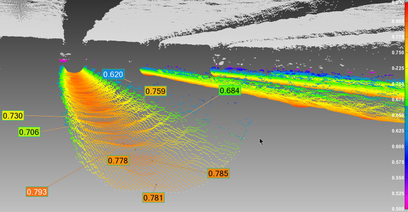
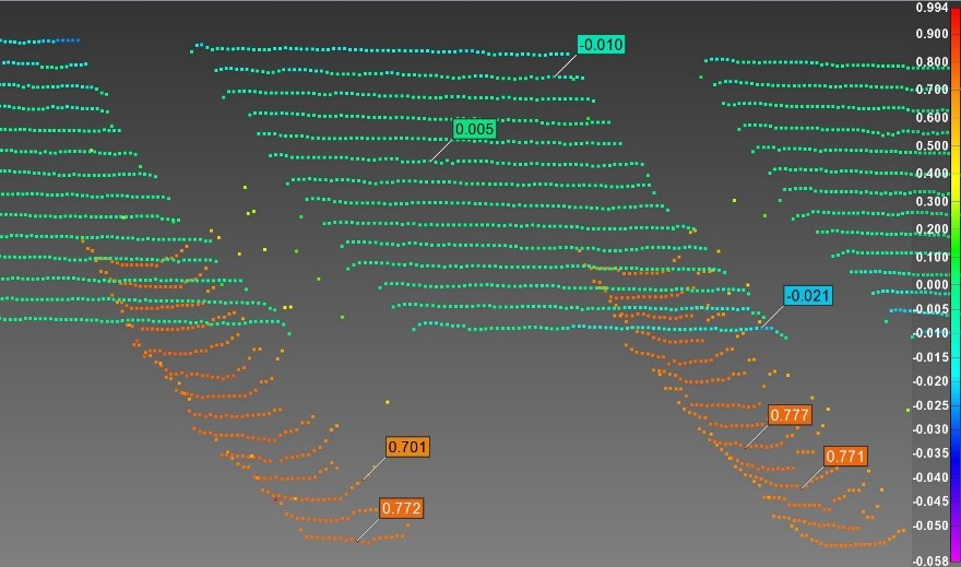
Zoom-in view of one of a CMP pad groove with tool marks on the groove bottom readily visible. Measurements are in mm.
CMP pad measurement example
A 10mm x 10mm area of a CMP pad surface was scanned with NOVACAM SURFACEINSPECT system, providing a 3D point cloud of micron-precision measurements for analysis.
In zoom-in view of the grooves, tool marks on groove bottoms are readily visible.
The depth of grooves was querried, with depth shown to vary between .768 and .793 mm.
Groove bottom shape analysis was performed. Perfect cylinders were fitted on each groove to obtain a mean radius measurement. Here, the measured radii of curvature were found to vary between 475 and 528 μm.
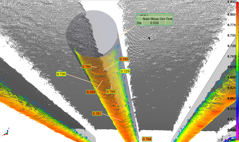
View from below of the CMP pad grooves clearly shows the tool marks of the bit used to machine the channels. Perfect cylinders were fitted on each groove to obtain a mean radius measurement. Here, the measured radii of curvature were found to vary between 475 and 528 μm
The challenge of measuring CMP pad grooves
Due to the narrowness of the groove opening, inspecting the full geometry of groove bottoms is difficult or impossible with touch probes or with optical systems that rely on triangulation.
In contrast, NOVACAM 3D metrology systems have no problem measuring even bottom corners of the steep walled grooves. This is thanks to the fact that they scan in collinear manner – i.e., the beam of light travels up and down along the same path.
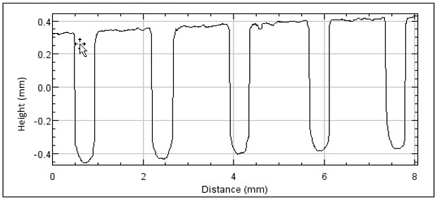
A simple linear profile of CMP pad indicates the depth and shape of the machined slurry-channeling grooves.
Long profiles for fast in-process measurements
Helping optimize the CMP pad inspection process, NOVACAM 3D metrology systems measure rapidly and efficiently with fiber-based optical probes. The probes are mounted on gantries or precision stages above the CMP pads.
Depending on their application requirements, manufacturers select from two basic types of probes:
- standard probes (part of NOVACAM OPTICAL 3D PROFILOMETER system) and
- galvo probes (part of NOVACAM SURFACEINSPECT system) which scan in a raster pattern.
Whichever type of probe is selected, scanning is performed in a point-by-point manner at a rate of 100,000 3D point measurements per second along user-defined scan paths.
Long-profile measurement is available and is prized in CMP measurement applications. It eliminates the need for time consuming tiling and stitching that would be required by microscope-type measurement systems.
A sparser scan of the CMP pad – such as this profile only every 1 mm – may be selected to track CMP pad groove shape and depth.
System benefits
Benefits to CMP pad manufacturers
With scan measurement data fed automatically and seamlessly into process control, CMP pad manufacturers are able to:
- Carry out 100% inspection of the pads
- Provide their customers with a QC report with each pad
- Log and trend measurements to optimize the use of consumables in their manufacture process
Benefits to facilities running CMP processes
Process managers are able to use the same 3D metrology system for:
- Monitoring of CMP pad surface geometry
- Measurement of surface pad conditioners
- Measurement of the wafers.
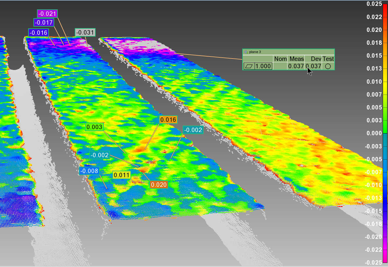
CMP pad land (top surface) analysis: the 3D point cloud of the measured top surface is displayed as a colour deviation map from a flat plane. The calculated GD&T flatness value is shown in the green callout.
Related links
Download application note “CMP Pad Metrology” [4 pages, PDF, 0.5 MB] for more details on this application
See products used for CMP measurement:
Contact us or request free sample analysis to learn how NOVACAM 3D metrology systems can benefit your CMP quality control